The entire air defense of Great Britain hinged on experimental technology called Radio Direction Finding (RDF). Today we know it as RADAR, its american name. But it was invented by the British, and without it the Dowding System would not have worked.
Radio Direction Finding works on the principal that if metal objects reflect radio waves. The RAF began investigating this concept in the 1930’s in hopes of building an EMF “death ray” to destroy incoming bombers. In January 1935, the head of the National Physical Laboratory’s Radio Department, R.A. Watson Watt was consulted about using electromagnetic radiation to damage aircraft or kill the crew. He determined that the power requirements were too high to be practical, but countered that he could possibly detect them with EMF radiation.
In February of 1935, Dowding funded a shoestring experiment by Watson Watt to test this concept. Although crude, using existing BBC radio signals, the results were promising. Immediately sensing the potential, Dowding scambled with the Air Ministry to fund development. Typically disinterested, the Air Ministry agreed, one one condition. The development of Dowding’s RDF towers could not interfere with grouse hunting.
How RDF Worked
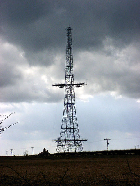
RDF Transmission Tower
RDF stations transmitted a pulsed radio wave from large vertical towers. When the radio waves encountered an incoming aircraft, it reflected energy back. Receiving antennas detected these reflected radio waves. These radio transmissions traveled in a wide “spotlight” beam pattern. Unlike modern radar, these stations would not rotate, so they could only “look” in one direction. Dowding placed his stations on the coast, looking out to sea.
Inside an operator’s hut, an RDF Operator watched a trace, a green horizontal line on a Cathode Ray Tube. When the RDF station received a reflection from an aircraft, a pattern appeared in the trace. RDF Operators called this an echo.
Determining Location
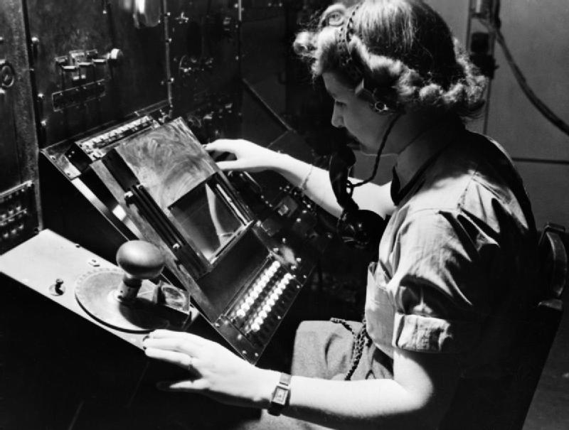
RDF Operator using viewing the CRT. Goniometer control is on the left.
A plastic scale attached to the CRT marked the distance away from the station in miles. Where the echo occurred on the trace indicated the range of the incoming aircraft. The RDF Operator used another device, called a goniometer to determine the echo’s bearing. By turning the goniometer dial back and forth, the RDF Operator determined the echo’s direction. Range measurements were typically accurate, but because RDF transmitted a floodlight beam, bearing readings were not precise.
Determining Number of Aircraft
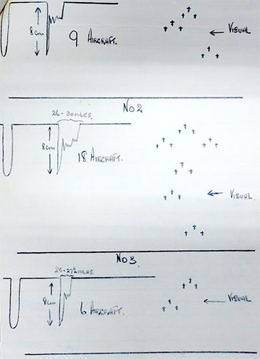
Sketches showing how different aircraft formations appear in the CRT trace
RDF stations were also capable of providing rudimentary information about the number of aircraft it was detecting. The shape of and number of peaks in the trace provided a rough picture of the number and formation of aircraft. If planes were more than 1.5 miles apart, they’d appear as separate peaks. If the formations were tighter, the peaks would merge, making identification more difficult. Converting the trace into a reliable picture of raid strength was highly subjective and required experience.
Accurate counting was an ongoing problem throughout the battle. Underestimations were common with inexperienced Operators. These mistakes led Controllers to scramble insufficient numbers of fighters for larger raids. During the war, the RAF never solved the problems associated with counting.
Determining Altitude
The RDF Operators also tried to determine the altitude of incoming aircraft. This was critical, because in a dogfight, altitude is advantage. Because RDF was rudimentary technology, this was also difficult. The RDF Operator would perform complex calculations based on trigonometry to determine the altitude. Based on the Operators mathematical skill this could be fraught with errors. Experiments with determining altitude also uncovered a fundamental weakness with early RDF: it couldn’t detect aircraft below 5,000 ft.
Chain Home
Dowding recognized that because RDF was experimental, it had considerable weaknesses. So he deployed the station in a network. The concept was that by using readings from multiple stations, the inaccuracies in their readings would be cancelled. Multiple wrongs making a right.
He organized the stations in a chain, placing each station 20 km apart. Any one station’s beams overlapped with its neighbors, so several RDF stations would detect the same incoming planes. This network, named Chain Home, became the backbone of Britain’s early warning system. By the outbreak of war, there were 21 Chain Home stations.
Chain Home Low
To address the weaknesses detecting aircraft flying lower than 5,000 feet, the RAF deployed a second type of RDF network: Chain Home Low. When activated in 1940, the Chain Home Low network addressed the vulnerabilities with Chain Home. RAF scientists based its design on Naval gun-laying radar. These units used a revolving, narrow beam, like modern radar. This characteristic made Chain Home Low more accurate at determining bearing, but its effective range was shorter, making it inadequate to replace Chain Home.
The RAF experimented with how to process information from both station types. Ultimately they decided that Chain Home Low information would pass through a neighboring Chain Home station. This became a logistical challenge for both the RDF Operators and the Filter Room personnel.